Working with vectors will become especially important in the coming sections and as your game development career grows. So now let’s apply some of the things you’ve learned.
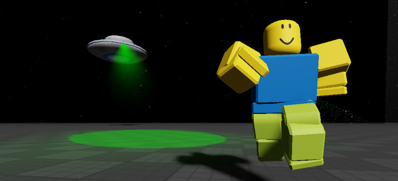
In this game, we’ll create an alien spaceship that patrols an area and searching for players. If a player is spotted, it will call a bombardment on the player’s location.
Let’s break this down.
The ship will patrol toward a random vector position. This position does not deviate too far from a home position and is be generated randomly once the ship reaches the destination.
A spotlight attached to the ship scans the area looking for players. We’ll use the dot product to determine if a player has been spotted.
The spotlight also needs some kind of visual representation. This will be an ellipse coincident with the ground sized to look like a spotlight. The position and shape of the ellipse will be calculated each frame.
A ground placement cannon will be positioned at a different location which will be called upon to fire at spotted players. The trajectory of the cannonball will be calculated when the cannon fires.
Figuring out the shape of the ellipse and the calculating the trajectory for the cannonball involve a bit of math so let’s work on those first.
Dimensions of an Ellipse
When a circular light source coincides with a surface at an angle, it forms an elliptical spotlight with a length proportional to the angle. This angle also slides the center of the ellipse away from the source so that the position where the light is shining and the center of the ellipse are not the same.
To calculate the shape and position for the ellipse we need to first decide on how to simulate the light itself.
One way to do this might be to attach a look vector to the ship’s position. Then each frame, rotate that vector slightly to simulate a light scanning the area.
Another way might be to create and track an imaginary position at ground level. Each frame, that position is moved some amount to simulate a scanning spotlight. Then the look vector between the ship and the position can be calculated.
The former will look better and more natural since it simulates a light being rotated at its pivot. However, it also requires more angle computation and needs to compensate for the movement of the ship.
The latter case looks natural enough and only requires keeping track of the ground incident position.
This also happens to be the position which the ellipse will be offset to so we’ll use this method.
The first thing is to figure out the length of the ellipse. In math speak, this means the major axis of the ellipse.
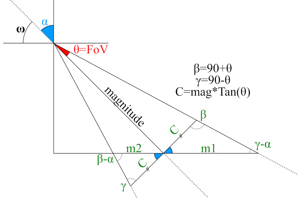
From the sideview of the projection, we can see that this is just a series of triangles. The lengths of m1 and m2 add up to the major axis, so those are the lengths we need to solve for.
Halving the field of view makes calculations easier so that’s the angle we will use. Whenever you encounter the FoV variable, just note that it is half of the actual field of view.
The Law of Sines tells us that:

Rearranging m1 and m2 to one side yields the equations:
The sum of m1 and m2 is the length of the major axis. Half of that is the semi-major axis a.
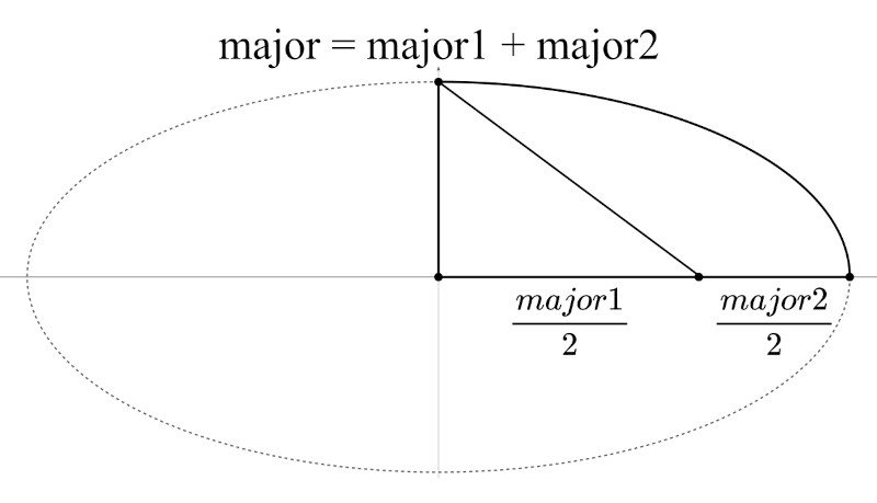
We have two equations for the eccentricity of an ellipse. For a conic section intersected by a plane, the eccentricity can be calculated from the equation:
Where ω is the angle the light makes with the horizontal axis.
Now we need an equation expressing the semi-minor axis b as a function of the semi-major axis and eccentricity.
The standard form for the eccentricity of an ellipse is given by:
Moving b to one side yields the equation for the semi-minor axis.
Trajectory of a Projectile
The standard equations for projectile motion are given by:
If you’ve take a ‘classical mechanics’ physics course, then these are already familiar to you. If you have not taken physics, fret not. They just describe an object’s trajectory.
x and y are the horizontal and vertical positions of an object. v is its velocity. The subscript 0 indicates an initial position/velocity. t is time. And lowercase g is acceleration due to gravity.
For this problem, we know the projectile starting position, the target position, and gravitational acceleration.
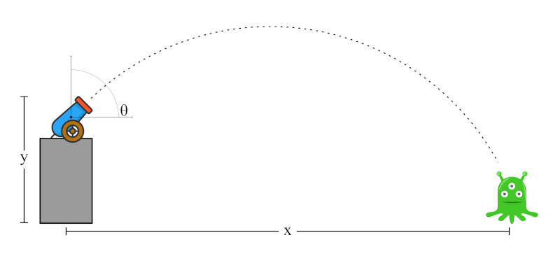
The distance the cannonball travels depends on how fast it is traveling horizontally and the time it is in the air.
However a projectile fired horizontally requires exceedingly high velocities to travel even modest distances and there is a practical limit to how fast it can travel.
So rather than ramping the projectile’s velocity, we can increase the time it is in the air by giving it an initial vertical velocity. In other words, it is launched at some angle above the horizontal.
This means there will be two unknowns: the initial velocity and the launch angle.
One of them needs to be constrained so we’ll manually define the launch angle so that just the launch velocity remains.
This can be broken down into a horizontal and vertical velocity using the trig functions.
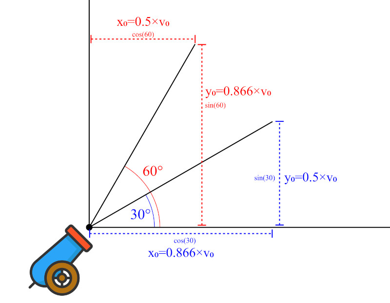
Looking at the figure, we can see that if the ball is launched at 30°, the horizontal velocity is 86% the speed of the launch velocity while the vertical velocity is 50%, making low angles good for “direct attack” cannons.
At 60°, the velocities are reversed and the cannonball is lobbed over a high arc. This is good if there are objects between the target and the cannon but also increases the time of flight, making fast moving targets harder to hit.
Because air resistance is not simulated, 45° is a tradeoff between both and gives the best distance for a given launch velocity.
Equation 1 is the distance a projectile travels at a given velocity and time. It can be rearranged to yield the time it takes a projectile to travel some distance for a given velocity.
The extent of that time is also limited to how long the projectile is in the air. Meaning it is dependent on gravity and the vertical velocity. This leaves us with equations 3 and 4.
Equation 4 is for finding the vertical velocity at a given time and not what we are looking for.
Equation 3 solves for the final vertical position which is already known. But is also has another piece to the puzzle: the initial vertical velocity. This looks most promising so let’s go with it for now.
I have my cannon perched on a turret, so there is a final vertical position that differs from the initial vertical position y0.
Gravity accelerates in the downward y direction, so that has to be negated.
Substituting in the equation for t, we get:
The velocities cancel out in the rightmost expression. And from the trig functions, we also know that:
Which simplifies to:
All of the other variables are known so now we just have to solve for v0.
